Studio
Photographs showing the Phonovision equipment first appeared in books and publications (notably ‘Television’) in the middle of 1928. Three pictures show a record turntable apparently linked to the drive shaft of the ‘camera’ which was hidden behind a wooden panelled wall. If this was the recording studio then the disc-cutting apparatus is noticeable by its absence. Given that the discs are professional-quality pressings from the Columbia Graphophone Company, they and their equipment were probably hired in only for the recording sessions with the studio photographs taken sometime after.
Those three photographs of the studio taken in 1928 gave enough information for me to extract the three-dimensional layout of the ‘studio’ and, using the disc on the platter as absolute dimensional reference established the sizes of the rest of the equipment.
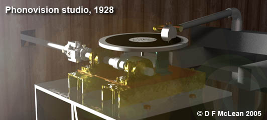
POYray simulation of the Phonovision ‘studio’.
Solely by studying the pictures, a surprising amount of supporting information can be extracted helping us understand how the system was meant to work.
Linkage Resonance
 As the horizontal drive shaft (disappearing into the wall on the left) turns, the worm gear transfers the rotation to the turntable. The universal joint (shown here in red) allows for slight misalignment in the drive shaft but would have caused problems . in the ‘Miss Pounsford’ recording. The heavy bearings (shown in blue) would have helped suppress vibration through the drive shaft. In the absence of any recording cutter equipment, a pick-up arm (highlighted in yellow) was poised above the disc platter, possibly only for the benefit of these pictures.
Gearing is consistent with ‘Phonovision’ discs

Detail of gearing (simulation)
The gear ratio of drive-shaft to turntable is the ratio of the sizes of both parts of the gear assembly (the worm gear shown green). Measured from the photographs, this ratio is 3:1. That means that for three turns of the drive shaft, the turntable turned once. If the drive shaft were connected directly to a Nipkow scanning disc able to scan one 30-line frame on each rotation, then there would be three 30-line frames on each rotation of the record turntable. This agrees exactly with the Phonovision discs.
The dummy head faces a black hole in the wall, the scanning aperture of the Baird ‘camera’. This, according to captions accompanying the original pictures, is the ‘Noctovision’ experimental set-up. ‘Noctovision’ was a Baird invention under development at the same time as Phonovision. It’s aim was to televise subjects without using visible light.

© Pitman 1931
Taking this all a bit further, we know the conventional way that record turntables turn (the way the ‘Phonovision’ discs turn). By following this through the gears to the drive-shaft, this means that the drive-shaft turned clockwise as it entered the wall in the picture above. In Baird’s early days he used large Nipkow discs to carry the large aperture lenses needed to gather the light. In the photograph above, the hole in the wall in front of the dummy has two large lenses visible. If there was no further gearing and with those size of lenses, I suggest that there is a large diameter Nipkow scanning disc behind the panelling and that where the dummy is sited is the area where the subjects were filmed.
The picture below illustrates this and reconstructs the lens spiral as per the Phonovision recordings. That is, the 1st line (lens) of each 30 line TV frame (one rotation of the disc) is innermost, the last line outermost on the Nipkow scanning disc.
